PTC Fuses in VEX Robots: A Guide
As a former VRC competitor, and later as an event volunteer, I’ve often seen teams running into problems with their robots’ PTC fuses. This usually manifests itself as certain motors “stalling” or failing to run temporarily, but running again after several seconds of inactivity. So, I thought I’d write up an overview on the configuration of a VEX robot’s PTC fuses and how it can affect robot design.
What is a PTC fuse?
Essentially, a PTC fuse is an electrical component whose resistance increases with temperature ("PTC" stands for "Positive Temperature Coeffecient"). PTC fuses are used in VEX robots to prevent motors form drawing too much current, damaging their internals or other sensitive electronics. When the current passing through a PTC fuse is above a rated amperage, the fuse begins to heat up. If it gets too hot, the resistance will become so high that no current is able to pass through the fuse. Once the fuse cools back down, current can again flow. For this reason, PTC fuses are sometimes known as "resettable fuses".
Where are PTC fuses located in VEX robots?
Each motor on a VEX robot is protected by 2 PTC fuses: one in the motor itself, and the other in the Cortex or Power Expander to which it’s connected. The Cortex contains 2 PTC fuses: One protecting ports 1-5 and another protecting ports 6-10. Further, another PTC fuse protects the ports on the power expander. Motors connected to the power expander are protected by the PTC fuse in the expander, and are not connected to the fuse on whatever Cortex port they’re connected to.
The image below shows a sample wiring arrangement for a bunch of motors, and the accompanying table shows which PTC fuses protect each motor.
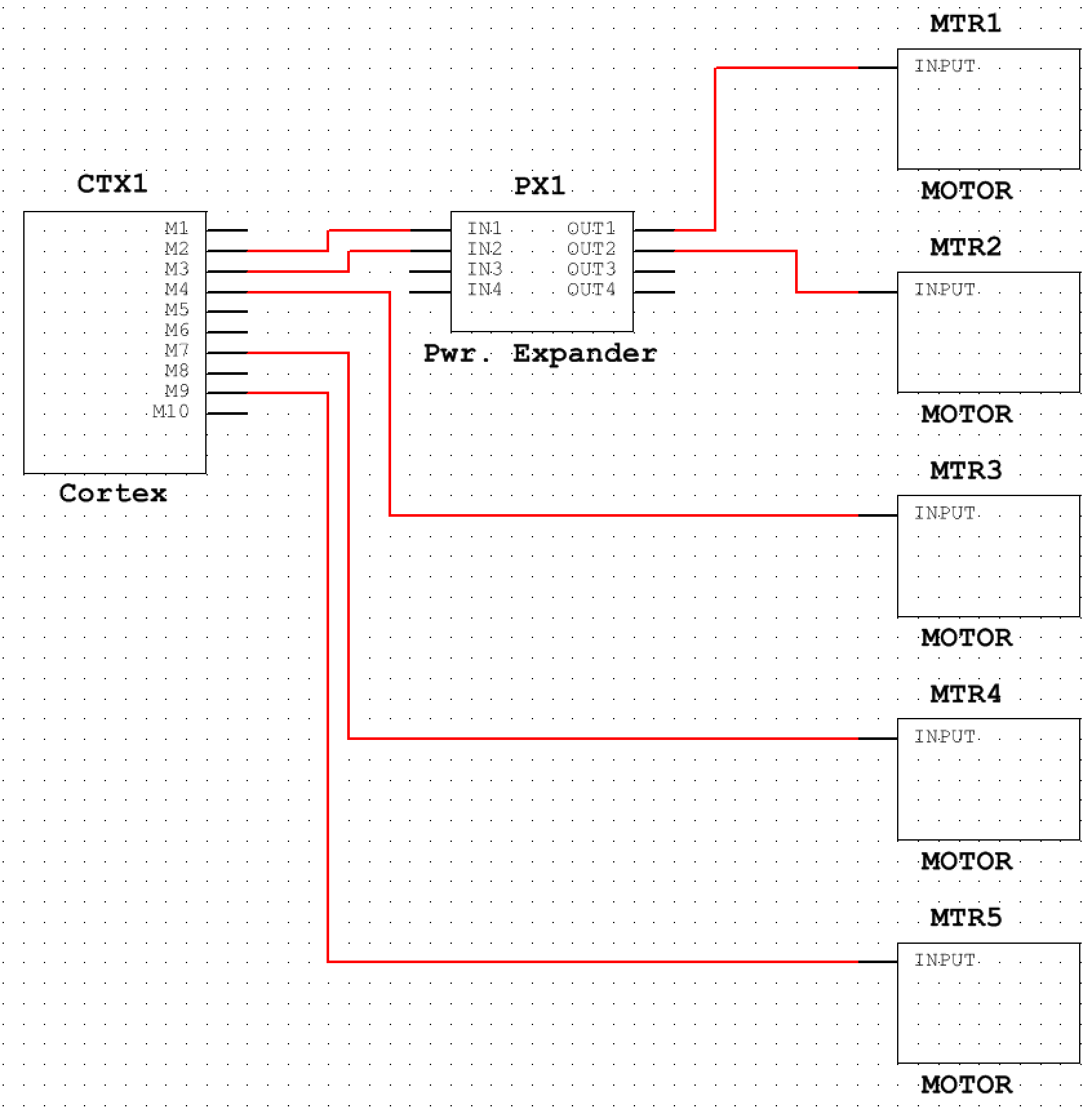
| Motor | Fuses |
|---|---|
| 1 | Motor 1, Power Expander |
| 2 | Motor 2, Power Expander |
| 3 | Motor 3, Cortex 1-5 |
| 4 | Motor 4, Cortex 6-10 |
| 5 | Motor 5, Cortex 6-10 |
Why is this important?
VEX forum user jpearman conducted testing of the PTC fuses used in the Cortex and motors, concluding that the PTC fuses in the Cortex/Expander will trip at 3 to 4 amps, while those in a 393 motor will trip at between 0.9 to 1.7 amps, depending on ambient conditions and variations in individual parts. Based on these values, if there are several motors connected to the same PTC fuse under simultaneous heavy load, it’s pretty easy to trip the Cortex/Expander PTC fuse, and temporarily disable every motor on that bank of ports, which can be disruptive or disabling during VRC match play.
How should this affect my robot design?
When designing a robot, you should think about which motors will be subject to heavy loads at what times, and plan how to connect motors to the Cortex accordingly, so that heavy loads are spread across multiple Cortex/Expander PTC fuses.
What if I'm tripping a PTC fuse in a motor?
If your robot consistently trips a motor PTC fuse, you should first examine the mechanism it’s powering. Minimizing friction, checking for slightly bent shafts, adding passive assistance (i.e., via rubber bands), or even adding more motors are all actions that could alleviate such problems. However, at busy tournaments, sometimes there isn’t time for PTC fuses to cool fully between matches, which can lead to reduced performance. In this case, some teams have reported success with industrial “freeze spray” products. You can also use upside-down cans of air (for cleaning keyboards and the like), which schools might already have, though my personal preference is for the freeze spray. A downside of using freeze spray, in my experience, is that some team members like to spray themselves and each other with it, which could be dangerous, and is certainly a waste of valuable freeze spray.